41 wiring water pump diagram
May 31, 2021 · Float Switch Connection Auto Manual Single Phase Water Pump Youtube Electrical Circuit Diagram Electrical Projects Water Pump s. Wiring Diagram For 220 Volt Submersible Pump Submersible Pump 1993 Ford Mustang Wiring Diagram 2001 Ford Mus Submersible Pump Submersible Well Pump Sump Pump . 44 Luxury Single Phase Submersible Pump Starter Wiring ... 27.3.2016 · Wiring color diagram for Tracker and ... on my navigation works but red and green dont then on my aerator pump noise coming from under dash and can’t hear my pump running it’s on a 2005 16.5 bass ... .my fish finders wont lite up…every thing else on the boat works…now its not in the water as its winter time here in ...
This information serves as a typical Spa or Hot Tub wiring diagram to help inform you about the process and electrical wiring ... Heater Dry Run Protection- A water flow sensor that prevents the heater from turning on until there is sufficient water flow. Pump Dry Run Protection- If the pump runs for 5 minutes and flow is not detected the ...
Wiring water pump diagram
Grundfos SQFlex Solar Water Pump Wiring Diagram . Click here to view, print. Wiring diagram . The alarm Grundfos Conlift1 LS is a small, compact lifting station with evaporators. The Conlift is suitable for the pump ing of condensate. describe Grundfos CM pump s. Sections give the Before installing the pump , check that the pump type and parts are as . A float switch is a mechanical switch that floats on top of a liquid surface. As the liquid level goes up or down, it moves vertically with the liquid level.... Shurflo Water Pump Wiring Diagram – rv water pump switch wiring diagram , rv water pump wiring diagram , shurflo 12v water pump wiring diagram , Every electric arrangement consists of various unique components. Each part should be placed and connected with other parts in particular way. If not, the structure won’t work as it should be.
Wiring water pump diagram. Bmw e90 coolant water pump fuse location and replacement e91 e92 e93 bmw 325i 328i 330i 335i 316d 318d 320d 325d 330d 335d 316i 318i 320i 323i 325xi 328xi 33. Bmw electric water pump wiring diagram . Read bmw e46 wiring diagram pdf images. 12vdc to 4 wire. I am using a bmw electric water pump on my hot rod. Wiring Diagram 2000 Smoker Craft Pontoon; Everbilt Sprinkler Pump Wiring Diagram ; 4.3 Vortec Spider Injector Plug Wiring Diagram ; 1762-ia8 Wiring Diagram ; Wfe-24 Water Feeder Wiring Diagram ; Lft Fishbone Diagram ; Man D Tec Els-sb Wiring Diagram ; General Electronic Typical Wiring Diagram Np 26687d; Recent Comments. Justwinwin on 5.3 ls1tech ... Place the heat shrink tubing over the. 3 wire well pump diagram s are more complicated and require a better. For the water to enter your house however you should also have your own pump . Black wires go to black wires and the green wire the ground goes to the ground wire. For more information about 220 volt wiring diagram 220 volt wiring diagram . Float Switch Connection Single Phase Water Pump what is float switch?float switch is a type of level sensor a device used to detect the level of liquid within...
water well pump wiring diagram – What’s Wiring Diagram ? A wiring diagram is a kind of schematic which uses abstract pictorial signs to show all the interconnections of elements in a system. Circuitry layouts are made up of 2 points: symbols that represent the elements in the circuit, and lines that stand for the links in between them. Usually your wiring diagram is either pasted to the inside of the door panel, or else contained in a plastic pouch inside the door itself. Either way, you must remove the door panel to get to it as described in section 5-2. If you already know how to read a … Nov 28, 2017 · Rv Net Open Roads Forum Tech Issues Water Pump Problem Need Help. Water pump wiring jayco rv owners forum how to replace a 12v in an harness camper trailer boat issue 1997 fleetwood shurflo 94 591 01 silencing kit third switch winnebago potable installation thor forums system diagram it all interactive for pump s signs your universal electrical accessories are plumbing fresh tank dump of the ... Before Installation. Well pump installation can be dangerous when dealing with water and electricity, so extreme caution must be taken. Before getting started, look up your owner's manual and read over the precautions and all other warnings before beginning the installation. The manual will contain important safety precautions, wiring diagram s, tools required for assembly, proper grounding ...
Dec 23, 2021 · 3 Wire Submersible Pump Diagram Diagram Base Website Pump 3 Wire Submersible Well Pump Wiring Diagram from zkl.512x512kahaniya.fun Water pump dry run guard full project with source code. Here is a picture gallery about 2 wire submersible well pump wiring diagram complete with the description of the image, please find the image you need. Diagram s --Typical Pump Installations. The information provided here is for educational purposes only. Technically qualified personnel should install pump s and motors. We recommend that a licensed contractor install all new systems and replace existing pump s and motors. Failure to install in compliance with local and national codes and ... Ignition on= pump on. Use a relay. Make 3 small bypass-holes in the thermostat to avoid hotspots in your heads if you are using a electric pump like the meziere/CSR. Those pump s do not have the recirculationexits like the mec pump has. Fan is more of a choice, manually by switch (look at the temp "all" the time). water pump pressure switch wiring diagram - What's Wiring Diagram ? A wiring diagram is a form of schematic which uses abstract pictorial symbols to show each of the interconnections of components inside a system.
Proform Electric Water Pump Wiring Diagram
There are just two things which are going to be present in almost any Shurflo Water Pump Wiring Diagram . The first component is symbol that indicate electric element in the circuit. A circuit is usually composed by many components. The other thing you will see a circuit diagram would be lines.

Electrical Wiring Diagram For Water Pump Motor Set
Heat pump thermostat wiring - A typical wire color and terminal diagram . As shown in the diagram , you will need to power up the thermostat and the 24V AC power is connected to the R and C terminals. The color of wire R is usually RED and C is BLACK. C is known as the common terminal. These two connections will ensure that there is power to the thermostat that you are …

Bmw Electric Water Pump Wiring Diagram Collection
From the diagram below of a TRRS jack, each of the arrows on the symbol corresponds to one of the Tip, Ring 1, Standard mm jack pinouts. The datasheet states that it's a 3-pole stereo jack socket - for the first plug in Figure 1. Wiring diagram showing stereo connections for mm headphone plug, Now,.

33 Shurflo Water Pump Wiring Diagram - Wire Diagram Source ...
PUMP 3 1. Check Valve Located at the top of the pump to prevent back flow into pump and hold the head of water in the system. 2. Torque Arrestor Installed directly above Submersible Pump to protect pump and well components from starting torque damage. 3. Safety Rope A safety line from the top of the well to the pump . 4. Pitless Adapter
Wiring Diagram For Water Pump - Wiring Diagram Schemas
DOWNLOAD. Wiring Diagram Images Detail: Name: goulds pump wiring diagram - Goulds Pump Parts Diagram Inspirational Irrigation Pump Irrigation Pump Rebuild Kit. File Type: JPG. Source: kmestc.com. Size: 93.56 KB. Dimension: 522 x 574. DOWNLOAD. Wiring Diagram Sheets Detail:

Water Lily Pond (1900) // Claude Monet French, 1840-1926
Jet Pump Wiring Diagram - wiring diagram is a simplified usual pictorial representation of an electrical circuit. It shows the components of the circuit as simplified shapes, and the capability and signal links in the midst of the devices. A wiring diagram usually gives opinion virtually the relative perspective and covenant of devices and ...
Shurflo Water Pump Wiring Diagram | Wiring Diagram
Wiring A 12v Water Pump Duet. Universal Electric Water Pump Relay Kit Autotrix Net. Water Pump Wiring 4x4earth. Shurflo Self Priming 12 Volt Diaphragm Water Pump 180 Gph 12in Ports Model Number 2088 343 435 Online In Vietnam B000ldbyew. Solar Water Pump Wiring Diagram Grand Technologies Ltd Facebook.

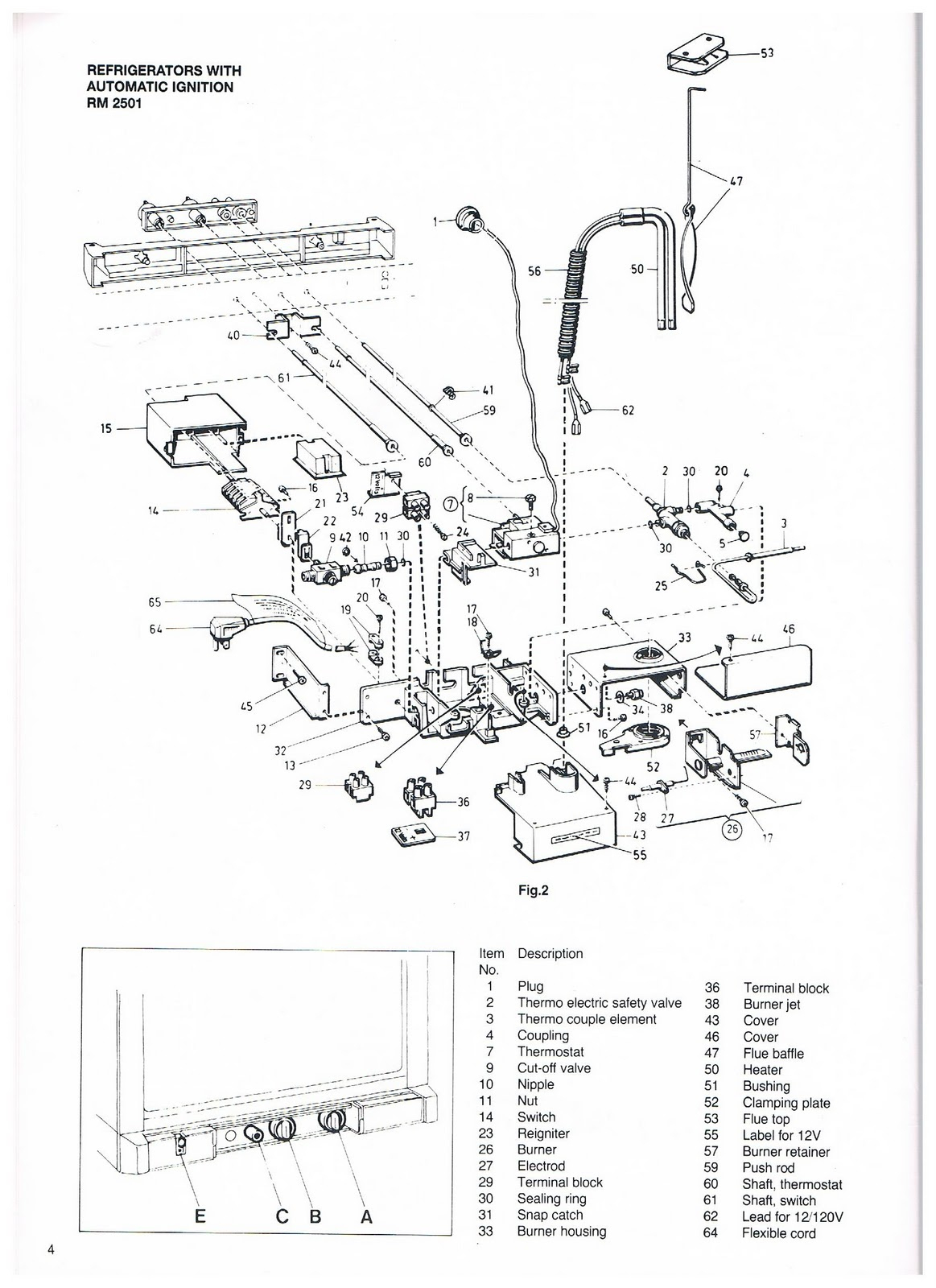
Elektische Ausrüstung—- Electrical installation
Float Switch Wiring Automatic Manual Single Phase Water Pump Controller Water Pump Youtube Electrical Circuit Diagram Water Level Switch Water Pump s. Shurflo 9300 Wiring Diagram For Pump ing Into A Pressurized Tank Submersible Well Pump Well Pump Water Pump s. Single Phase Submersible Pump Starter Wiring Diagram On Water Control Panel Inside To ...

Goulds Water Pump Wiring Diagram
Wiring Diagram s Trane Geve 006 060 Gehe 072 180 300 Exhf 070 Exvf. Water Source Heat Pump Axiom Horizontal Vertical Geh Gev ½ 5 Tons 60 Hz Wshp Prc017h En November 2018. Trane Vertical Stack Wshp Installation And Maintenance Manual Manualzz. High Efficiency Horizontal And Vertical Water Source Comfort System.

Image from page 295 of "Cyclopedia of applied electricity : a general reference work on direct-current generators and motors, storage batteries, electrochemistry, welding, electric wiring, meters, electric lighting, electric railways, power stations, swit
6.12.2016 · Today I hear to write about the submersible pump control box wiring diagram , in this post you will completely understand the 3 wire submersible pump wiring diagram which is a single phase submersible pump motor.Why we called a single phase submersible motor a 3 wire submersible, that we also know that we have two wire in single-phase power supply.

water drop on bucket photo
Well pump wiring diagnosis & repair: this article describes troubleshooting a submersible well pump that was causing tripped circuit breakers and that pump ed water only at a slow, reduced rate and pressure. Ultimately using some simple electrical tests the homeowner traced the water pump problems to a nicked well pump wiring circuit wire.

Septic Pump Wiring Diagram | Free Wiring Diagram
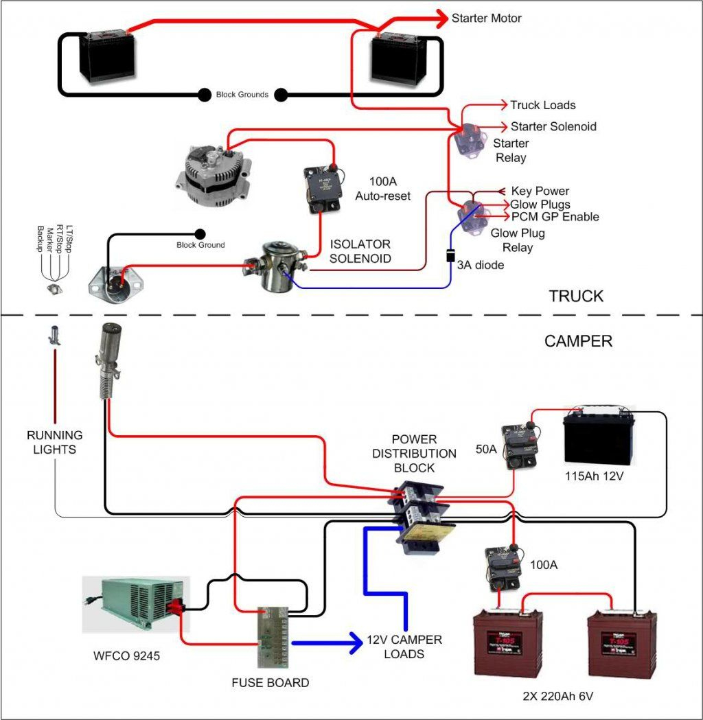
24.7.2021 · Interactive electrical wiring diagram for DIY camper van conversion (skoolie, RV). Hover your mouse / click on any product to learn more.
Electric water pump control.gif
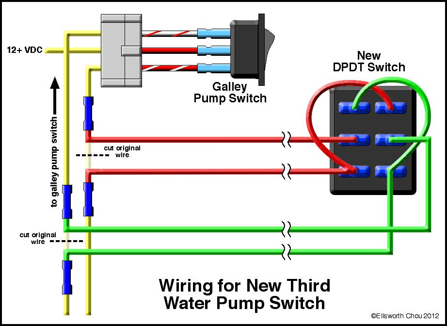
wiring diagram 2 way switch to operate 1 water pump machine#saklartukarbuatoperasikanmesinairmanualjadisemiotomatis

Hotsy Pressure Washer Wiring Diagram Download
Well Pump Motor Wiring Diagram - wiring diagram is a simplified all right pictorial representation of an electrical circuit. It shows the components of the circuit as simplified shapes, and the capability and signal contacts with the devices. A wiring diagram usually gives assistance virtually the relative slope and settlement of devices and ...

water droplets
Proform Electric Water Pump Wiring Diagram . Currently, the water pump and electric fan and grounded to the cylinder head and the the first diagram is their '' electric fan relay harness kit ''. Electric water pump s are nothing new in the world of high-performance and even street-going engines. Through the years, though, they have.
Shurflo Water Pump Wiring Diagram For Your Needs
INSTALLATION WIRING DIAGRAM - 115VAC - TWO-WIRE PUMP S For 115 Vac motors exceeding 16 full load amps, use magnetic starter to avoid damage toMascontrol®. See separate magnetic starter wiring diagram .! WARNING 22 Remove pressure switch from surface pump and wire Mascontrol® directly to pump . IMPORTANT

light reflected on water at daytime
10+ Water Pump Wiring Diagram Single Phase. He was a recognized genius known as the water wizard. This project is environmental related project. Wiring diagram s single phase hook up diagram or what colours go together. I need answers to why it wouldnt work similar to the single phase if the only thing that differs is the voltage requirements.

Water Pump Motor Automatic and Manual Control | Float ...
Just purchased a csr electric water pump an not sure the safest or best way to wire it Wiring diagram as suggested Dagram is shown with. SMALL BLOCK FORD ELECTRIC WATER PUMP NOTE: If this water pump is to be used with a front engine motor plate, longer bolt-up hardware not Incorrect wiring of this pump will cause damage to the pump motor and/or your engine.

Water Pump Pressure Switch Wiring Diagram - Database ...
74fa2 Water Pump Pressure Switch Wiring Diagram Digital Resources. Intellitec Wiring Diagram Top Electrical Wiring Diagram . 1583086853000000. Https Www Rainharvest Com Info Rainflo Rainflo Pump Installation Instructions Pdf. Country Coach Wiring Diagram Today Wiring Schematic Diagram .
13 Water Pump Pressure Switch Wiring Diagram - Free Wiring ...
Pentax Water Pump Wiring Diagram . By Ahmad Jamaluddin January 04, 2020 Post a Comment. Leo Water Pump Shazam Enterprises Investments Ltd Pentax Versa Hd Endoscopy Machine Bma Bazar What We Offer Packaged Pump s Systems Ltd Packaged Pump s Pentax Ap Series Cast Iron Deep Well Bore Pump s Catalogus Pump s Pump ing 2011 By Henk Schenkels Issuu Faqs On ...

photo og water
Heat Pump Thermostat Wiring Chart Diagram - HVAC - The following graphics are meant as a guide only. Always follow the manufacturer’s instructions for both the thermostat and the HVAC system. Additional articles on this site concerning thermostats and wiring can help you solve your problem or correctly wire a new thermostat.

body of water during golden hour
Wiring a Water Well Pump Controller and Switch: To wire up a pump in a water well is a relatively small project you can do yourself (assuming you are the homeowner and local codes allow for this). Many well drillers are not licensed and finding a licensed electrician can add unnecessary time and costs to the job.
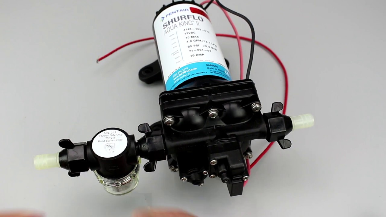
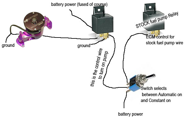
Wiring my electric water pump
Shurflo Water Pump Wiring Diagram – rv water pump switch wiring diagram , rv water pump wiring diagram , shurflo 12v water pump wiring diagram , Every electric arrangement consists of various unique components. Each part should be placed and connected with other parts in particular way. If not, the structure won’t work as it should be.
Electric water pump wiring - Third Generation F-Body ...
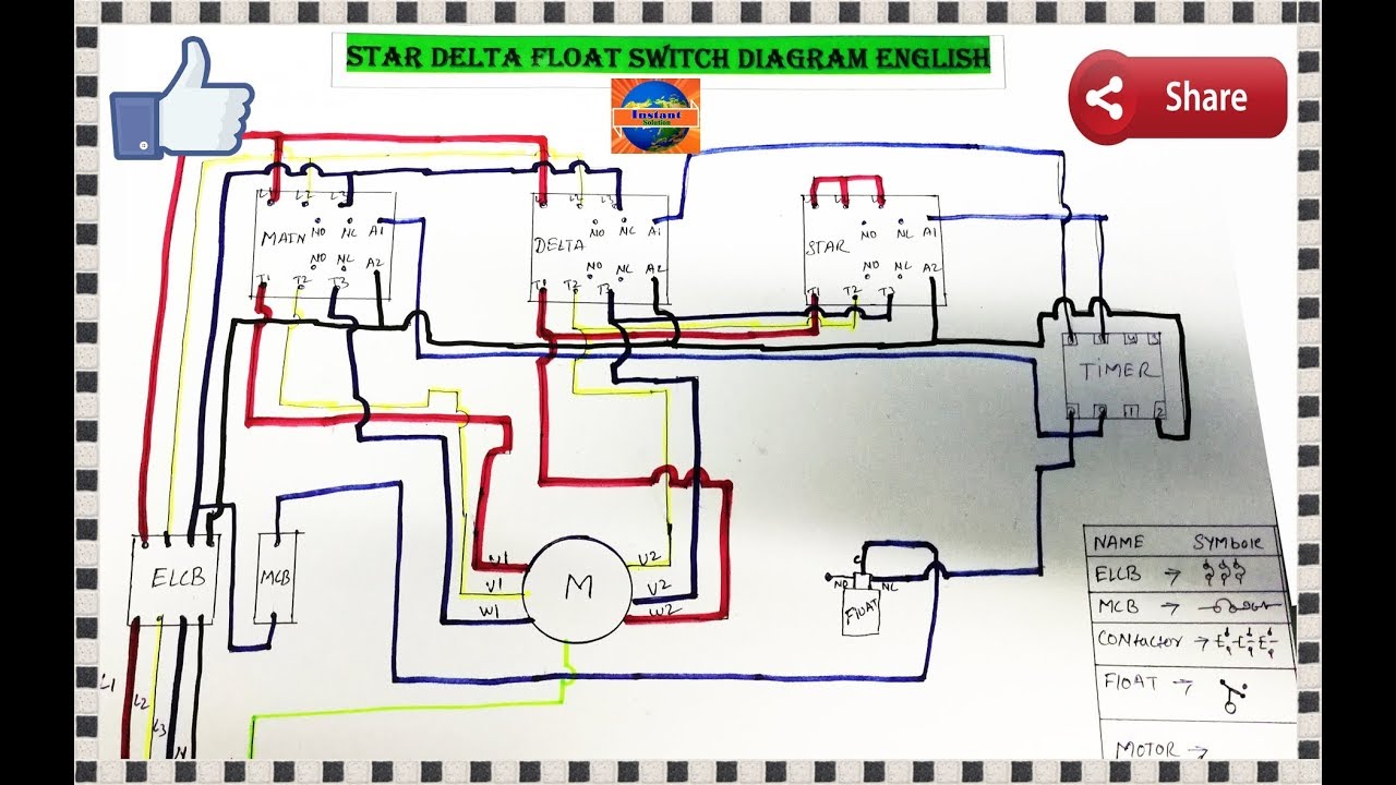
A float switch is a mechanical switch that floats on top of a liquid surface. As the liquid level goes up or down, it moves vertically with the liquid level....
1100W 110V DC Solar Water Pump | inverter.com
Grundfos SQFlex Solar Water Pump Wiring Diagram . Click here to view, print. Wiring diagram . The alarm Grundfos Conlift1 LS is a small, compact lifting station with evaporators. The Conlift is suitable for the pump ing of condensate. describe Grundfos CM pump s. Sections give the Before installing the pump , check that the pump type and parts are as .
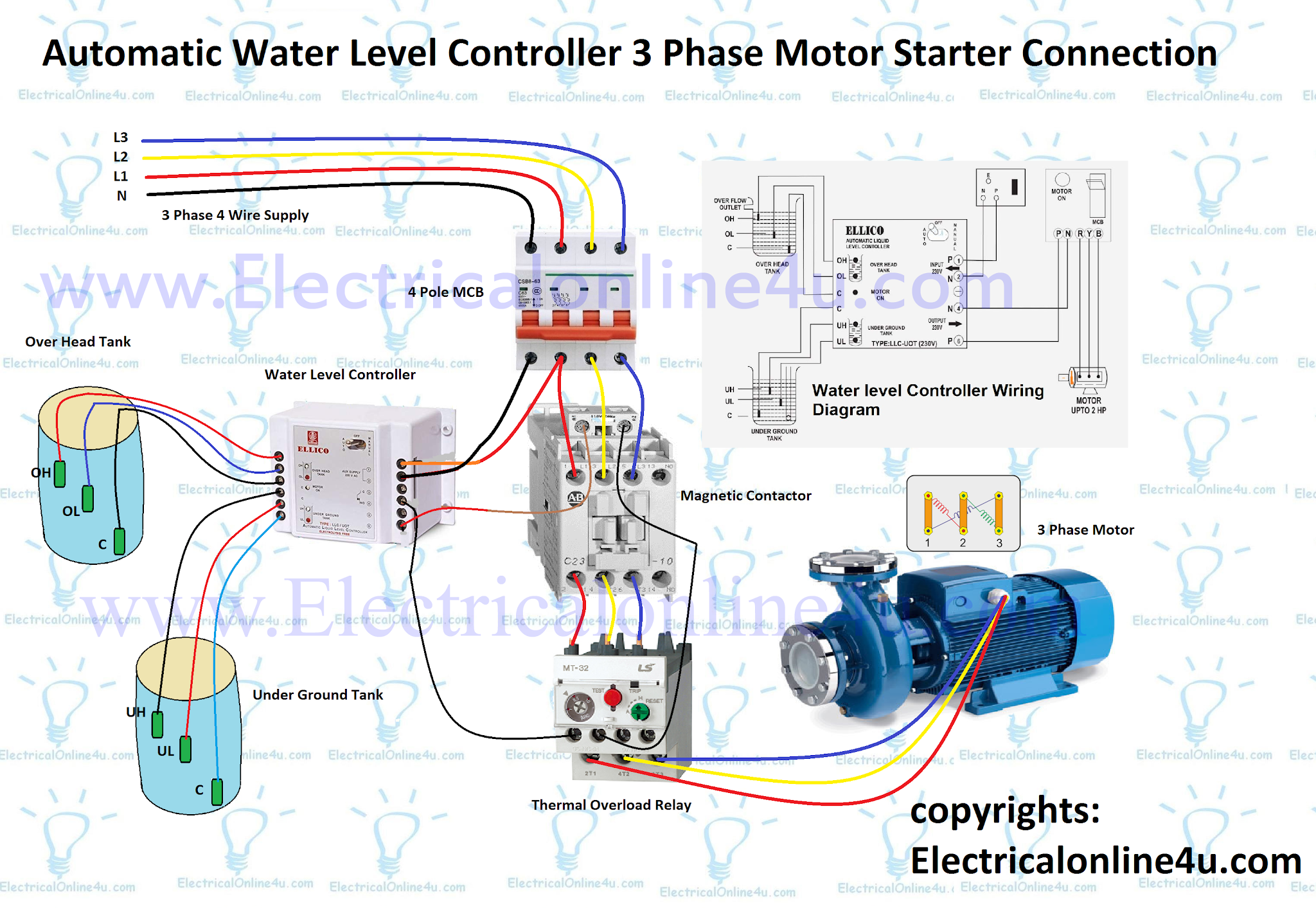
Automatic Water Level Controller Wiring Diagram For 3 ...

Hydria (Water Jar) (480-470 BCE) // Attributed to the Orchard Painter Greek; Athens
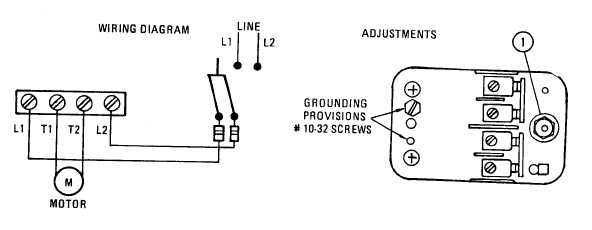
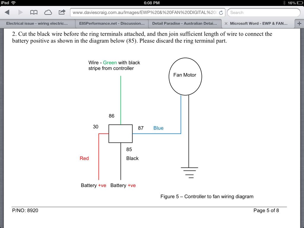
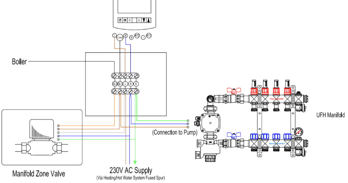
Figure 6. Water Pump wiring diagram

Maidstone ROYAL OBSERVER CORPS,Group HQ 57 London Road, Maidstone.

Shurflo Water Pump Wiring Diagram - General Wiring Diagram

Still Life: Apples and Green Glass (1925) // Charles Demuth American, 1883-1935
Wiring Diagram: 26 Shurflo Water Pump Wiring Diagram

Bmw Electric Water Pump Wiring Diagram - Cars BMW

Monochrome, Power Lines, Winlaton Mill, Tyne & Wear, England.
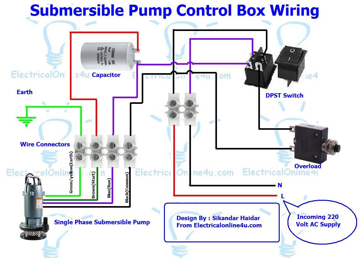
Submersible Pump Control Box Wiring Diagram For 3 Wire ...

Circuit diagram of water pump control system | Download ...

Goulds Submersible Pump Wiring Diagram Download

Water Lilies (1906) // Claude Monet French, 1840-1926
Shurflo Water Pump Wiring Diagram | Wiring Diagram
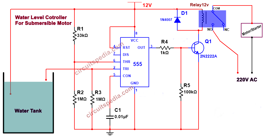
Automatic Water Pump Controller Circuit for submersible ...

unknown
0 Response to "41 wiring water pump diagram"
Post a Comment